
Accurate and reliable electrical testing is essential for both professionals and hobbyists working with electronics. The following guide offers a step-by-step approach to understanding and utilizing your versatile measuring tool. With the right knowledge, even the most complex electrical readings become straightforward and manageable.
This guide will explore essential features, settings, and tips for safe operation. Whether you’re measuring voltage, current, or resistance, understanding the functionality of each mode ensures precise results. Dive into practical advice designed to help users avoid common pitfalls and achieve consistent performance.
Gain confidence in troubleshooting, diagnosing circuits, and performing routine checks. By mastering the functions and applications, you’ll be fully equipped to handle various tasks efficiently, from simple home projects to more advanced electronic repairs.
Overview of the Mastercraft Digital Multimeter Functions
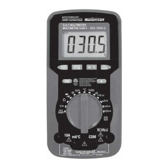
This section provides a comprehensive look at the capabilities and features of the measuring device. Understanding its functions allows for precise testing and diagnostics of various electrical components and circuits.
Core Measurement Modes
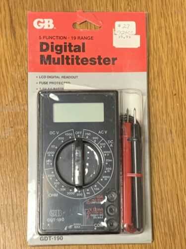
The tool offers several key measurement modes, enabling users to evaluate electrical properties in different environments. The primary functions include evaluating voltage, current, and resistance. Each of these modes serves a distinct purpose in diagnosing and analyzing electrical issues, ensuring reliable performance in diverse tasks.
Additional Features and Settings
In addition to core measurement modes, the device includes specialized settings such as continuity testing, diode checks, and capacitance measurement. These features help verify the integrity of connections and components, providing deeper insights into system performance. Additional configurations like auto-ranging and data hold enhance usability and precision.
| Function | Purpose |
|---|---|
| Voltage Measurement | Measures the electrical potential difference between two points. |
| Current Measurement | Determines the flow of electric charge in a circuit. |
| Resistance Measurement | Assesses the opposition to current flow within a component. |
| Continuity Test | Checks if there is a continuous path for current flow. |
| Diode Test | Verifies the forward voltage drop in semiconductor diodes. |
| Capacitance Measurement | Measures the storage capacity of capacitors. |
How to Set Up Your Multimeter
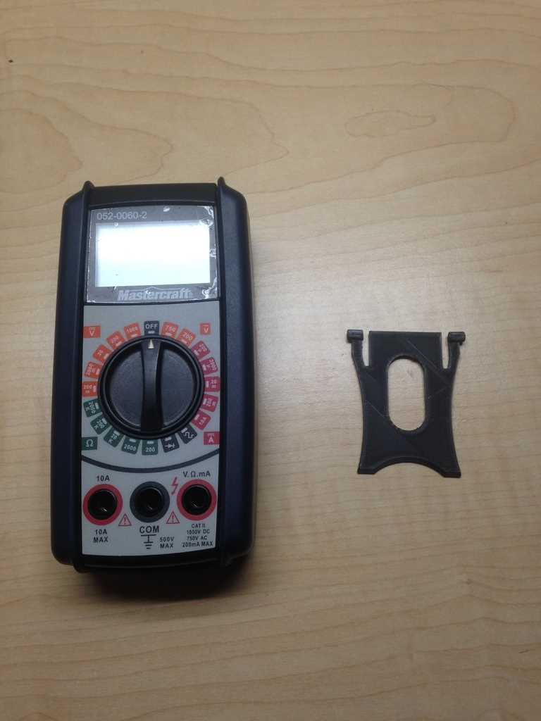
Before diving into measurements, it’s important to ensure that your tool is properly prepared. By setting up the device correctly, you’ll guarantee accurate readings and a smoother experience. Here’s a step-by-step guide to getting everything ready.
- Start by inserting the batteries. Open the compartment at the back and place the batteries according to the marked polarity.
- Connect the test leads. The black lead should be plugged into the common (COM) port, while the red lead typically goes into the port marked for voltage and resistance measurements.
- Familiarize yourself with the settings dial. Different measurement types are indicated by symbols. Select the one that matches the reading you plan to take.
- If your device has a backlight or other optional features, now is the time to ensure these are working properly.
- Check that the screen is clear and displaying correctly when the device is powered on.
With the setup complete, your tool is ready for use. Proper preparation makes all the difference in obtaining precise and reliable measurements.
Using the Mastercraft Multimeter for Voltage Measurements
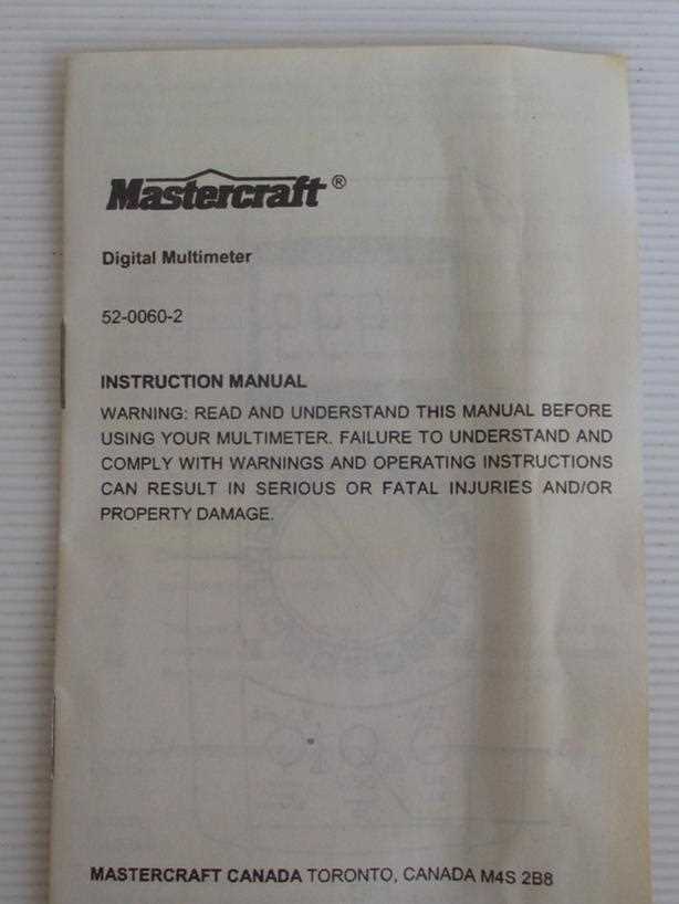
Understanding how to measure voltage is essential for safely working with electrical circuits and devices. This section outlines the key steps involved in accurately assessing both direct and alternating current, ensuring reliable readings without compromising safety.
Preparing the Device
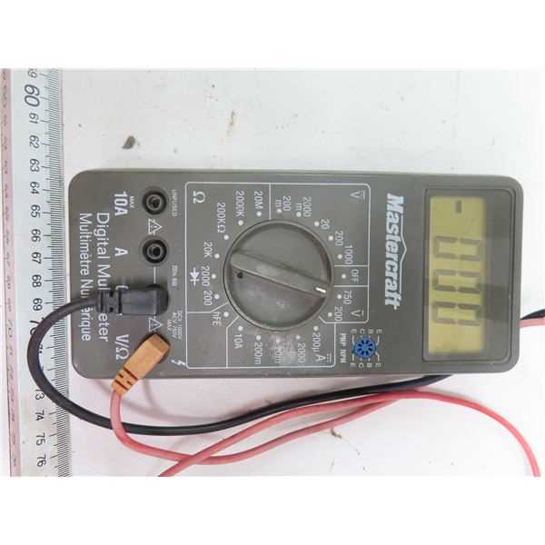
Before measuring, ensure that the selector is set to the correct type of voltage (AC or DC). Connect the probes to the appropriate terminals: the red probe typically goes into the port marked for voltage, while the black probe connects to the common (COM) port. Double-check that the range is suitable for the expected reading to avoid inaccurate results or damage.
Performing the Measurement
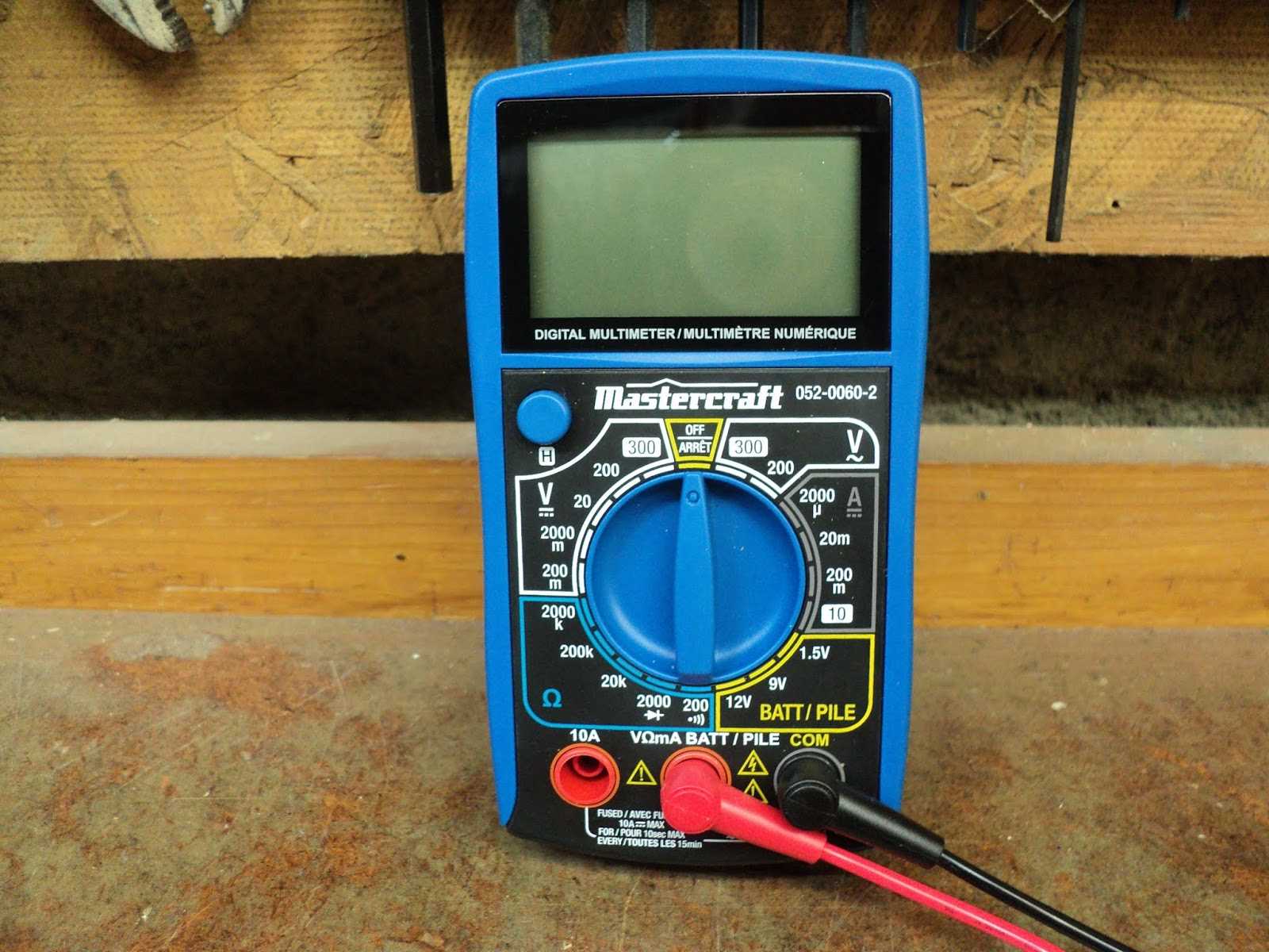
Place the probes on the points where voltage needs to be assessed–red to the positive side, black to the negative or ground. For alternating current, polarity doesn’t matter. Once the probes are in place, a stable reading will appear on the display. Take note of the value, ensuring it aligns with the expected range. After completing the process, safely disconnect the probes and reset the device as needed.
Testing Continuity and Resistance with Accuracy
Accurately measuring continuity and resistance is essential for ensuring the reliability and performance of electrical circuits. Understanding how to perform these checks allows for the detection of breaks, faulty connections, and the evaluation of resistive components, contributing to safer and more efficient electrical systems.
Understanding Continuity Testing
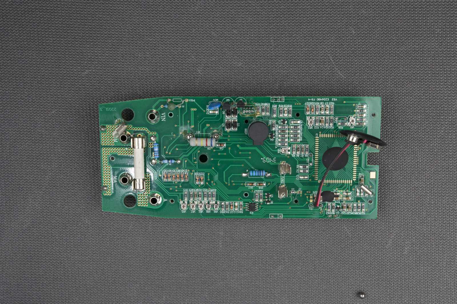
Continuity testing verifies whether an electrical pathway is complete and capable of carrying current. When performing this test, a clear signal indicates an unbroken path, while the absence of a signal suggests a break or poor connection. This process is especially useful for identifying faults in wiring, switches, and fuses.
Accurately Measuring Resistance
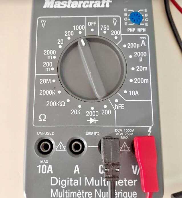
Resistance measurement determines the opposition within a circuit to the flow of current. Proper technique involves ensuring that all power is off and that the component is isolated. Different ranges are used depending on the expected resistance level. Accurate readings help assess the condition of resistors and other components, allowing for better diagnostics and maintenance.
Advanced Features: Diode and Capacitance Testing
Among the specialized functions offered by this measuring tool are tests designed to check diodes and measure capacitance. These features are vital for anyone dealing with electronic components, allowing accurate assessment of the state and functionality of circuit elements. This section explains how to utilize these options effectively, ensuring reliable results when working with different electrical systems.
For diode testing, the device applies a small voltage through the component, helping determine whether it conducts current in one direction only, as a healthy diode should. A forward voltage reading indicates the diode is working properly, while a reading showing no conductivity suggests a potential fault.
Capacitance measurement is used to verify the capacity of capacitors, essential for diagnosing issues in circuits that depend on energy storage. By measuring capacitance, you can confirm whether a capacitor is operating within its expected range or requires replacement. Understanding how to access and interpret these readings will enhance troubleshooting skills and ensure more precise maintenance and repairs.
Common Troubleshooting Tips for Multimeter Users
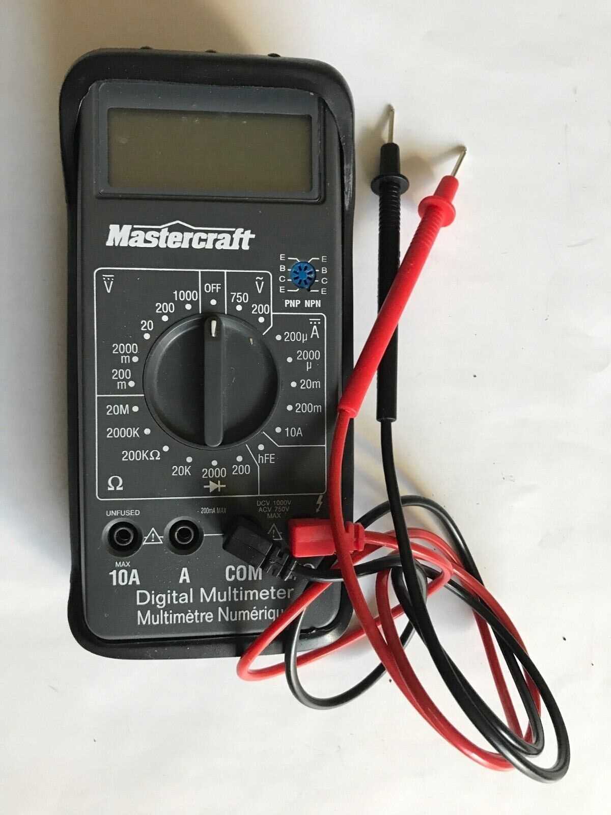
Understanding and resolving issues with your measuring device can significantly improve its performance and extend its lifespan. By following a few essential steps, users can diagnose common problems and ensure accurate readings. This section provides practical advice for effectively managing issues you might encounter with your instrument.
- Check the Battery: A weak or depleted battery can cause inaccurate readings or complete device failure. Replace the battery if the display becomes faint or the device does not power on.
- Inspect the Leads: Damaged or improperly connected leads can lead to erroneous measurements. Ensure that the leads are intact and securely plugged into the appropriate terminals.
- Verify the Settings: Using incorrect settings can result in misleading measurements. Double-check that the dial or selector switch is set to the correct function for the measurement you are attempting to take.
- Test Continuity: If the device seems unresponsive, check for continuity in the internal circuits. This can help identify internal faults or broken connections.
- Consult the User Guide: If issues persist, refer to the user guide for specific troubleshooting instructions and error codes. This can provide valuable insights into resolving complex problems.
- Perform Calibration: Regular calibration is essential for accurate measurements. Follow the manufacturer’s recommendations for calibration to maintain optimal performance.
- Clean the Device: Dust and debris can affect the functionality of your tool. Gently clean the exterior and connections with a soft, dry cloth to avoid interference with performance.
By adhering to these troubleshooting tips, you can address common issues and ensure that your measuring tool functions effectively for your needs.